A sound card as an A/D converter for a seismograph
 Marcin Polkowski
Translated from Polish. Originally published on morony.pl on 9 Oct 2016.
Part 5 of 5 in the series Homemade seismograph
- A homemade seismograph – first attempt
- Homemade seismograph – step two
- Homemade seismograph – first recordings
- A seismic recorder
- A sound card as an A/D converter for a seismograph
Today I received an email with a question about my earlier posts on building a simple seismic sensor (Homemade seismograph – a first attempt and Homemade seismograph – step two):
Hello,
I'm a geophysics student at AGH University of Science and Technology and a scout leader in the Polish Scouting and Guiding Association (ZHP). I'm preparing activities for young people to popularize seismology. We wanted to build a seismograph following your idea, but one thing is unclear to me – how exactly should the coil be connected to the computer's sound card? Unfortunately, I couldn't find the answer to this question in the article. I would be very grateful for a reply.
Kind regards, Marek Ziobro
Every email like this means a lot to me, because it means the content I create is valuable. Today I decided to answer publicly on the blog – I think the answer may be useful to someone else too.
The coil used in the seismometer is just an ordinary winding of wire with two ends. When the magnet moves inside the coil, the change in the magnetic field induces a voltage, that is, a potential difference between the two ends of the wire. The value of this voltage is proportional to how fast the magnetic field changes – the faster the magnet moves, the higher the voltage. You can of course measure a constant voltage with a multimeter, but in our case we want to measure how the voltage changes over time. Voltage as a function of time can be measured with an oscilloscope. If you don't have an oscilloscope at hand, you can make do with a computer sound card with a microphone input. The signal from a microphone is a voltage that varies in time, exactly as in the case of a seismic sensor. Some sound cards in desktop computers also have so-called line-in inputs, which work very similarly.
Of course, a sound card won't be a perfect oscilloscope (let alone a seismic recorder), because:
- It has a limited input voltage range – this is very important, because exceeding the maximum allowed voltage can damage the card. Check the exact values in the documentation for your card model. It works at the default sampling rates for audio (44.1, 48 kHz), which is far too much, but better too much than too little. It is quite noisy, which matters when recording weak signals. It usually has low resolution.
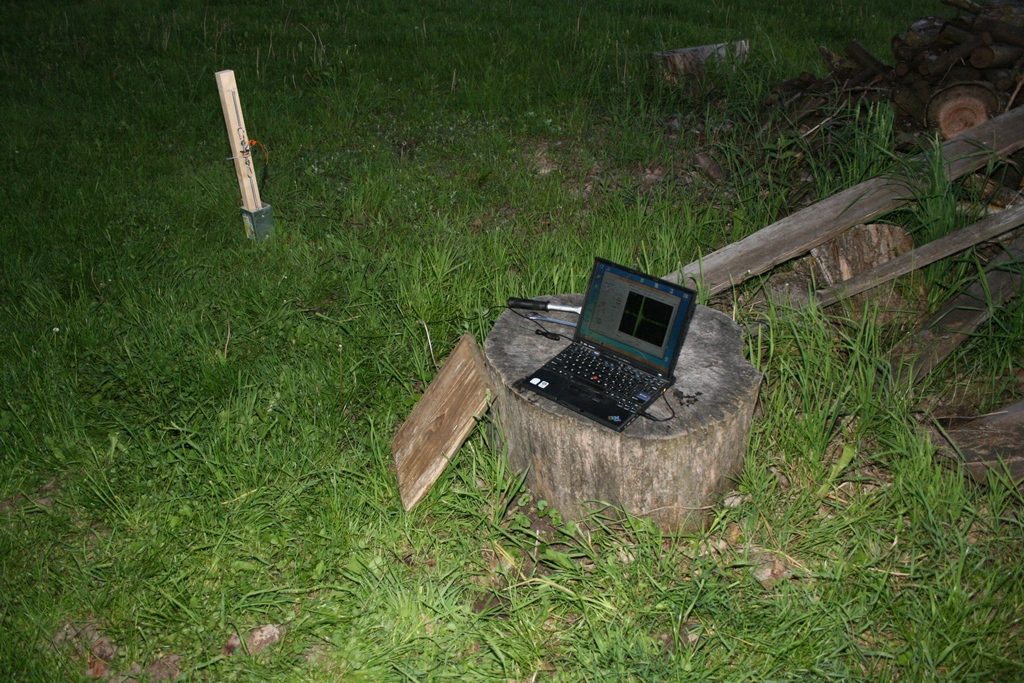
For the connection itself, you'll need a 3.5 mm jack plug (mono or stereo). Connect one end of the coil wire to ground, and the other to the positive terminal (for a stereo plug, to the L or R channel). Swapping the coil wires will affect the direction of the measurement: positive voltage for movement up or down – for starters this doesn't matter at all, but for more in-depth interpretation it's worth knowing and keeping track of. Sometimes it will be easier to buy a cable that ends in a jack plug (e.g. a headphone extension cable, or a cable for connecting a music player to a radio), cut it and join the wires. With a stereo cable, be careful not to connect the coil to the L and R channels, because then it won't work – one end has to go to ground. I used exactly this kind of modified cable:
On the computer you can use any sound recording software, or a special program that emulates an oscilloscope: Zelscope or Soundcard Oscilloscope. You can see the latter in my old photos (this photo is from 2006, which is why I had a CRT monitor in the workshop): 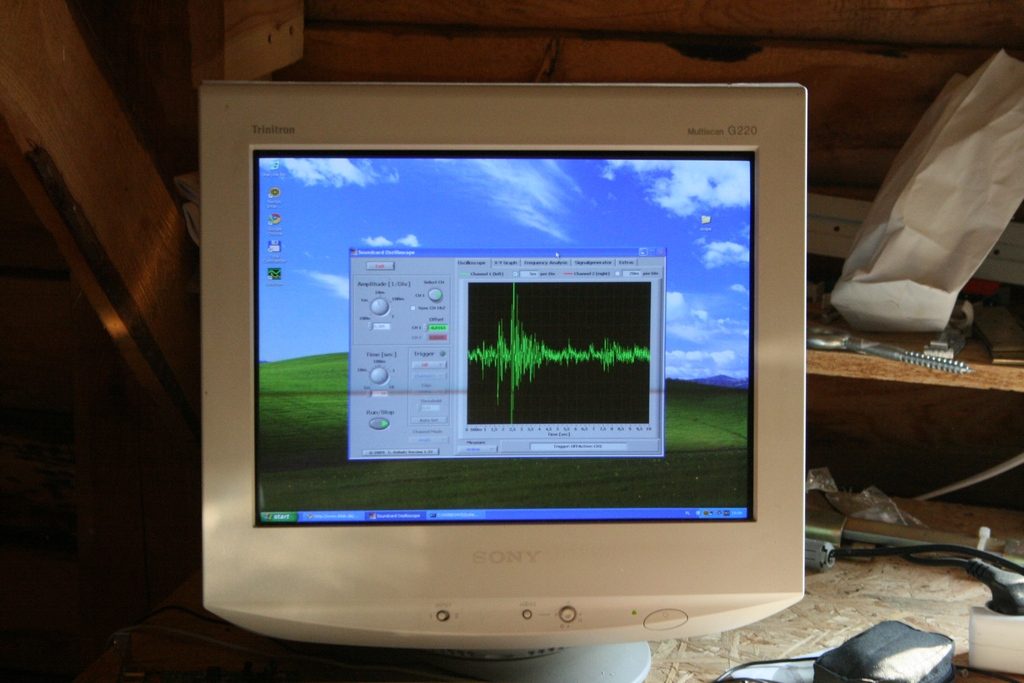
Best regards, and as always, I look forward to your emails!
Join me on Wednesday at 8 pm for a new post – this week it will be about floating-point numbers.
That was the last part of Homemade seismograph. Start from part 1