A seismic recorder
 Marcin Polkowski
Translated from Polish. Originally published on morony.pl on 30 Nov 2011.
Part 4 of 5 in the series Homemade seismograph
I've already touched on recording seismic waves when I built and presented a vibration sensor – a geophone. Back then I used the microphone input of a computer sound card as the recorder. Unfortunately, a recorder like that has many drawbacks: its sensitivity is low relative to the expected signal amplitude, it picks up noise from the computer components around it, and its resolution is low.
Professional seismic recorders are standalone devices that let you connect 1 or more geophones and convert the analog signal into a high-resolution digital one while keeping noise low and timing perfectly synchronized. Unfortunately, such devices are very expensive, and with prices starting at several thousand dollars they're out of reach for the ordinary amateur mortal.
The idea of building a recorder myself came up right away (and that was at least six months ago). The project is still in progress, but the hardest part is behind me. I decided to use the best components available, so as to achieve the highest possible quality. I don't want to share the technical details here – I suspect the wider audience isn't directly interested in them. I'm always happy to hear your questions and will answer them as best I can.
Of the technical aspects, the analog-to-digital converter chip itself is worth presenting. I chose a converter from Texas Instruments designed specifically for seismic applications, the ADS1282 – a tiny chip with 32-bit (!!!) resolution. The chip is only available in an SMD package, which isn't friendly for testing on a development board. To deal with this, I designed a printed circuit board for the chip and its peripheral circuitry, so that the whole thing could be connected to a microcontroller and powered on the development board. The board rendering looked like this: 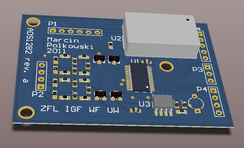 I had the board manufactured from my design by a professional company in Gdańsk. I carefully soldered on all the components, and the board, ready to be connected, looked like this:
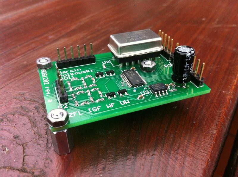
The finished board was a success for me, but connecting it correctly to the microcontroller (an ATmega32) and reading data from the converter took a good few days of work.
I tried to modify the whole circuit on the development board in such a way that I could use it as the basis for a large printed circuit board, with a geophone connection on one side and a USB output to the computer on the other. That board isn't ready yet; right now the whole circuit works, but on the development board. There are even two independent channels prepared for two geophones: 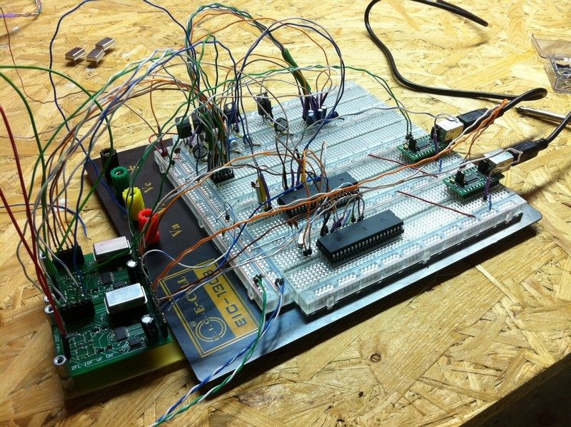
I'm sharing this with you because a lot of work has been done and the basic goal has been achieved. The circuit works! I don't want to go into how much money this work has eaten up, because I'd scare myself. It wouldn't have been possible without the measurement equipment lent to me by the Department of Lithospheric Physics at the Institute of Geophysics, University of Warsaw (IGF UW). I still intend to finish the project (lack of time is a real nuisance) and to prepare a device "at a commercial level" that can be used for real measurements and experiments in the field. I'd like the whole thing to be ready (at least a few units) by the summer of 2012.
Let me remind you that I'm not an electronics engineer, so each stage of the work was a bit of a challenge for me, and often a matter of groping around in the fog…
Next in Homemade seismograph: A sound card as an A/D converter for a seismograph →